
FEATURED BRANDS


%201.webp?width=813&height=429&name=unnamed%20(18)%201.webp)
%201.webp?width=813&height=429&name=unnamed%20(19)%201.webp)
![]()
Contact our Team of Experts Today
-
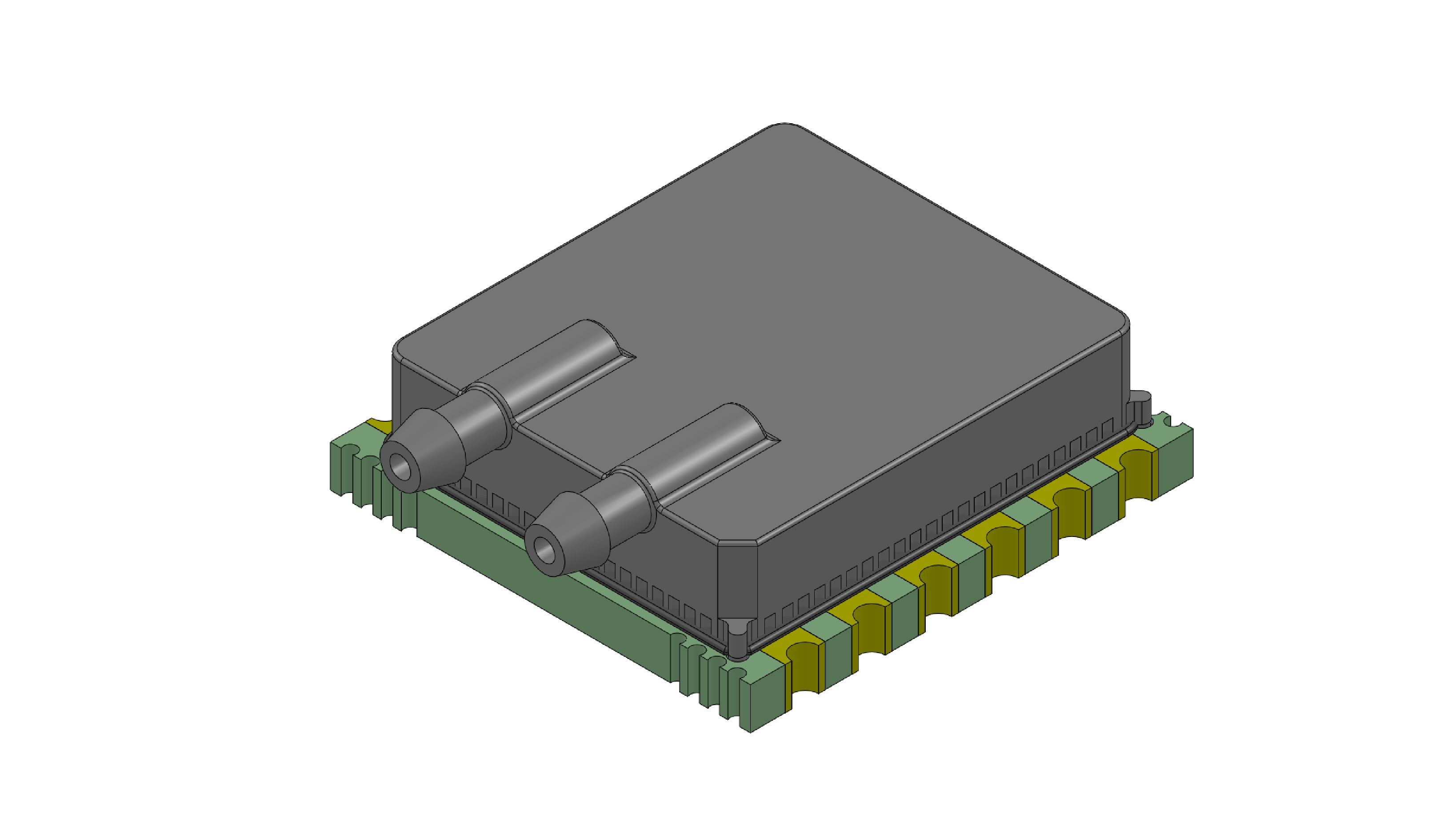
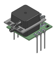
AUAV Series
Dual Sensors in a Single Package, Simultaneous Measurement ...
-
AABP Series
AABP Series- Coming Soon!
-
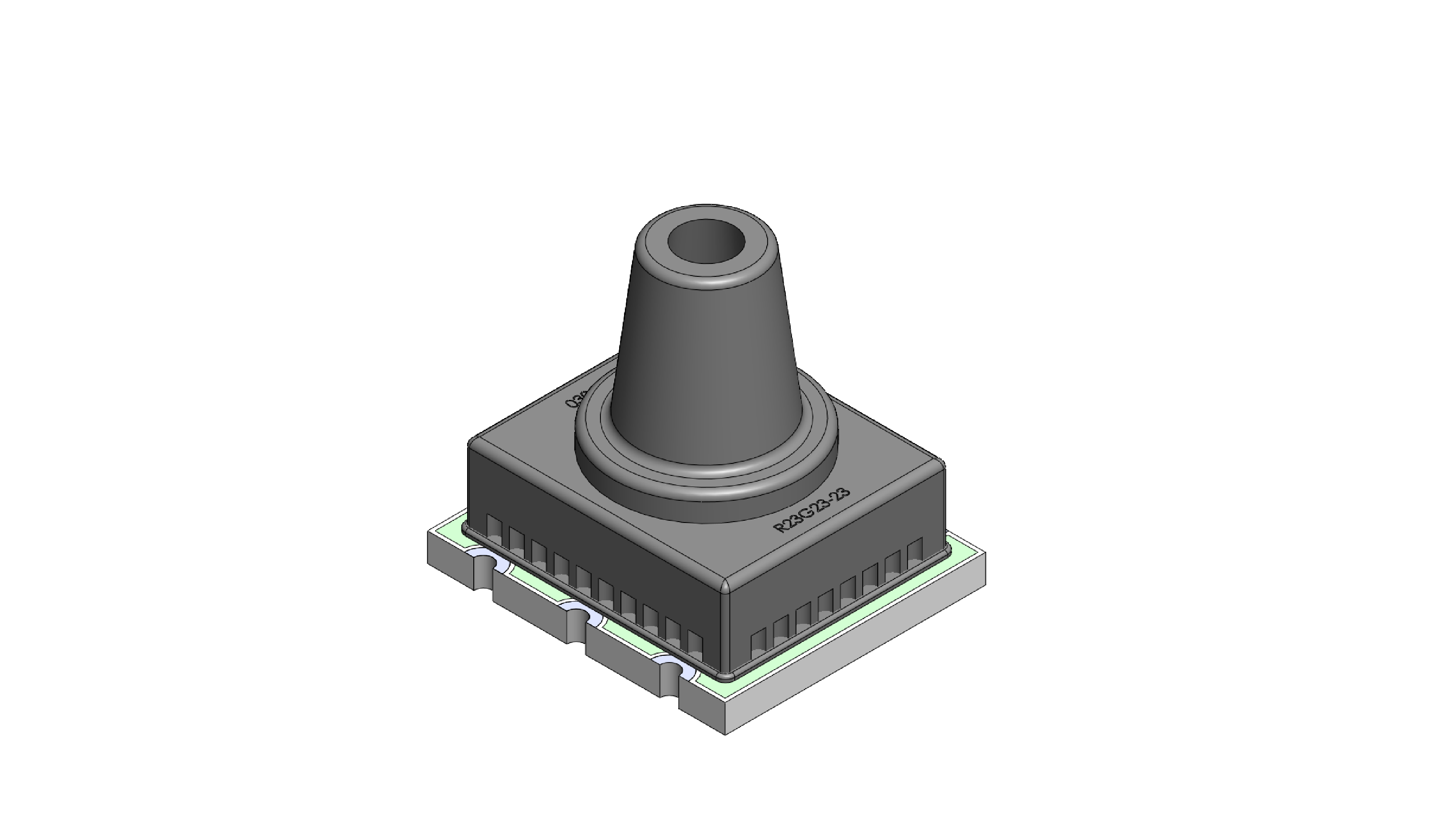
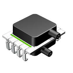
MLDX Series
5 inH2O to 100 PSI Pressure Ranges, matched pressure port ...
-
.png?width=250&height=250&name=ELVH%20(1).png)
ELVH Series
0.5 up to 30 inH2O and 1 up to 150 psi and 100 mbar up to ...
-
DLHR Series
0.5 to 60 inH2O, 1.68V to 3.6V Supply Voltage
-
Custom Sensor Solutions
Based on your unique application, a customizable or ...